
Cell Phone Jammer: A Guide to Building Your Own

A signal jammer for cell phones is a piece of electronic equipment that functions to impede and weaken radio signals used for communication between a mobile phone and a cell tower. The basic operation of the device is to utilize the same frequency range as the targeted handset, thus interfering with the ability of the caller and receiver to communicate efficiently.
It is effective in blocking the transmission of signals from networks including UMTS, 3G, CDMA, GSM, and PHS.
Components Needed for Building a DIY Cell Phone Signal Jammer
| COMPONENT | USAGE |
| Resistor R1 | Emitter Loading |
| Resistor R2 | Base Biasing |
| Capacitor C1 | Frequency Generation |
| Capacitor C2 | Feedback |
| Capacitor C3 | Feedback |
| Capacitor C4 | Noise Reduction |
| Capacitor C5 | Coupling |
| Capacitor C6 | Coupling |
| Capacitor C7 | Decoupling |
| Transistor Q1 | Amplification |
| Inductor L1 | Frequency Generation |
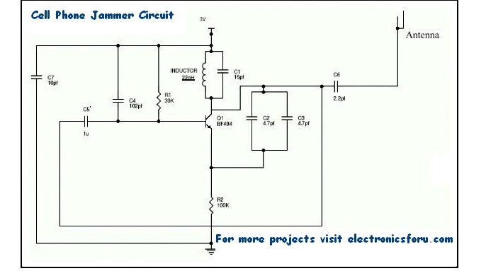
Cell Phone Signal Jammer Circuit
For any jammer circuit, it’s essential to have three important subcircuits.
RF amplifier
Voltage Controlled Oscillator
Tuning circui
These 3 circuits, when combined together form an efficient cell phone jammer circuit.
Cell Phone Signal Jammer Working
1.RF amplifier circuit comprises transistor Q1, capacitors C4, C5, and resistor R1. This RF circuit amplifies the signal generated by the tuned circuit. The amplified signal is given to the antenna through capacitor C6. It blocks DC and allows only the AC component of the signal to be transmitted.
2.When transistor Q1 is turned ON, the tuned circuit at the collector turns ON. The tuned circuit consists of capacitor C1 and inductor L1. This acts as an oscillator with zero resistance. It produces very high frequency with minimum damping.
3.When the circuit is ON, voltage is stored in the capacitor. Once the capacitor is completely charged, it allows charge to flow through the inductor. When current flows through the inductor, it stores magnetic energy corresponding to the voltage across the capacitor. At a certain point, the inductor reaches its maximum and the charge or voltage across the capacitor turns to zero.
4.Now the magnetic charge through the inductor decreases and the current charges the capacitor in opposite or reverse polarity. The process repeats and after a while, the inductor charges the capacitor and becomes zero.
5.This process runs till internal resistance is generated and the oscillations stop. RF amplifier feed is given through capacitor C5 to the collector terminal before C6. The capacitors C2 and C3 generate pulses in a random fashion (noise) at the frequency generated by the tuned circuit.
6.The RF amplifier boosts the frequency generated by the tuned circuit. The frequency generated by the tuned circuit and the noise signal generated by the capacitors C2 and C3 is combined, amplified, and transmitted.
Calculation of Mobile Frequency Jamming
Different countries and regions utilize specific frequency bands for mobile phones. In urban areas of Canada, the primary band is 1900 MHz, while 850 MHz serves as a backup in rural areas. Meanwhile, the USA uses either 850 or 1900 MHz bands depending on the area. Europe, Asia, Africa, and Oceania generally rely on the GSM 900 and 1800 bands as standard. In some countries, like Russia, local carriers have licenses for the 450 MHz frequency to provide CDMA coverage.
This variety of frequencies creates a challenge for developing a jammer that covers all possible bands. Nonetheless, a formula exists to calculate the necessary values for each band.
When it comes to blocking cell phone signals, the values of the inductor (L1) and capacitor (C1) can be altered based on the frequencies that need to be blocked. For example, if the mobile phones in the area work at 450 MHz, the blocking signal needs to be generated at 450 MHz with some noise. This noise will cause the cell phone receiver to be unable to understand which signal to receive, resulting in a blockage of cell phone signals.
It’s important to note that the tuning frequency, such as 450 MHz, is specific to this example and can vary depending on the frequency range of the cell phones in the area. Other cell phone jammers for different frequency ranges can be designed in a similar way.
However, it’s important to keep in mind that the signal range for these jammers is very weak, allowing for coverage of only about 100 meters. Despite this limited range, the blocking of cell phone signals can be an effective way to ensure privacy or deter unwanted phone calls in a specific area.”
Please note that the circuit provided can only block signals within a 100-meter radius. However, it is important to acknowledge that usage of this type of circuit is banned and illegal in most countries. It’s worth noting that this circuit is often used in TV transmission and remote-controlled toys.
If you find that the circuit is not working correctly, you may want to try increasing the values of the resistor and capacitors within the circuit. Be sure to use the provided formula to do so.
Additionally, keep in mind that the power supply for this circuit should not exceed 3 volts. By following these guidelines, you can ensure that the circuit operates effectively and within safe limits.”
- 4g Signal Booster
- Best Cell Phone Booster For Rural Areas
- Cell Booster
- Cell Booster for Home
- Cell Phone Antenna
- Cell Phone Booster
- Cell Phone Booster Antenna
- Cell Phone Booster For Home
- Cell Phone Signal Booster
- Cell Service Booster
- Cell Signal Booster
- Cell Signal Booster for Home
- Cellular Booster
- Cellular Signal Booster
- Homemade Cell Phone Signal Booster
- Mobile Booster
- Mobile Network Booster
- Mobile Phone Signal Booster
- Mobile Signal Booster
- Mobile Signal Booster For Home
- Network Booster
- Phone Booster
- Phone Signal Booster
- Signal Booster
- Signal Booster For Home
- Verizon Signal Booster
-

1. Anti Track Vehicle Car GPS Signal Blocker Jammer 10 Meters
$30.60
$25.50 -

2. Broad Spectrum Mobile Phone Signal Jammer
$51.00
$30.60 -

3. In Car Use GPS Signal Jammer Blocker
$30.60 -
 All Frequency Signal Jammer")
4. Portable GPS(L1 L2 L3 L4 L5) All Frequency Signal Jammer
$195.50
$178.50 -


