
How to Build a Cell Phone Jammer
A cell phone Signal jammer is an electronic device that blocks the transmission of signals between a cell phone and a base station. By using the same frequency as a mobile handset, the signal jammer creates strong interference in communication between the caller and receiver.
It is effective in blocking the transmission of signals from networks including UMTS, 3G, CDMA, GSM, and PHS.
DIY Cell Phone Signal Jammer – Components Required
| COMPONENT | USAGE |
| Resistor R1 | Emitter Loading |
| Resistor R2 | Base Biasing |
| Capacitor C1 | Frequency Generation |
| Capacitor C2 | Feedback |
| Capacitor C3 | Feedback |
| Capacitor C4 | Noise Reduction |
| Capacitor C5 | Coupling |
| Capacitor C6 | Coupling |
| Capacitor C7 | Decoupling |
| Transistor Q1 | Amplification |
| Inductor L1 | Frequency Generation |
Cell Phone Signal Jammer Circuit
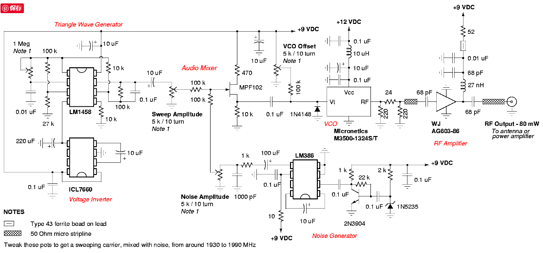
For any jammer circuit, it’s essential to have three important subcircuits.
- RF amplifier
- Voltage Controlled Oscillator
- Tuning circuit
These 3 circuits, when combined together form an efficient cell phone jammer circuit.
Cell Phone Signal Jammer Working
- RF amplifier circuit comprises transistor Q1, capacitors C4, C5, and resistor R1. This RF circuit amplifies the signal generated by the tuned circuit. The amplified signal is given to the antenna through capacitor C6. It blocks DC and allows only the AC component of the signal to be transmitted.
- When transistor Q1 is turned ON, the tuned circuit at the collector turns ON. The tuned circuit consists of capacitor C1 and inductor L1. This acts as an oscillator with zero resistance. It produces very high frequency with minimum damping.
- When the circuit is ON, voltage is stored in the capacitor. Once the capacitor is completely charged, it allows charge to flow through the inductor. When current flows through the inductor, it stores magnetic energy corresponding to the voltage across the capacitor. At a certain point, the inductor reaches its maximum and the charge or voltage across the capacitor turns to zero.
- Now the magnetic charge through the inductor decreases and the current charges the capacitor in opposite or reverse polarity. The process repeats and after a while, the inductor charges the capacitor and becomes zero.
- This process runs till internal resistance is generated and the oscillations stop. RF amplifier feed is given through capacitor C5 to the collector terminal before C6. The capacitors C2 and C3 generate pulses in a random fashion (noise) at the frequency generated by the tuned circuit.
- The RF amplifier boosts the frequency generated by the tuned circuit. The frequency generated by the tuned circuit and the noise signal generated by the capacitors C2 and C3 is combined, amplified, and transmitted.
Mobile Frequency Jamming Calculation
Mobile phones operate at different frequency bands in different countries. For Canada, the 1900 MHz band is the primary band, particularly for urban areas. 850 MHz is used as a backup in rural areas. The USA uses 850 and 1900 MHz bands, depending on the area. Europeans tend to use the GSM 900 and 1800 bands as standard. Middle East, Africa, Asia, and Oceania also use these frequency bands. In Russia and some other countries, local carriers have licenses for 450 MHz frequency to provide CDMA coverage.
The use of different frequencies makes it difficult to have a jammer for all frequencies. However, the below-mentioned formula can be used to calculate the required values.
F = 1/(2*pi*sqrt(L1*C1))
Depending on the frequencies you need to block, the values of the inductor (L1) and capacitor (C1) can be altered.
For example, if mobile phones in your area work at 450 MHz, you need to generate 450 MHz with some noise to act as the blocking signal.
Now the cell phone receiver will not be able to understand, which signal to receive. We have successfully blocked cell phone signals.
Here, 450MHz is the tuning frequency. Cell phone jammers for other frequency ranges are designed similarly. However, the signal range is very weak. Thus, this circuit works only for a range of 100 m.
Note
- This circuit can block signals only within a 100-meter radius.
- Usage of this type of circuit is banned and illegal in most countries.
- This circuit is also used in TV transmission and remote-controlled toys.
- If the circuit is not working properly, try increasing the resistor and capacitors values in the circuit. Use the formula given above.
- The power supply for the circuit should not exceed 3 Volts.
We have more such interesting DIY Electronics Projects for you.
-

1. Anti Track Vehicle Car GPS Signal Blocker Jammer 10 Meters
$30.60
$25.50 -

2. Broad Spectrum Mobile Phone Signal Jammer
$51.00
$30.60 -

3. In Car Use GPS Signal Jammer Blocker
$30.60 -
 All Frequency Signal Jammer")
4. Portable GPS(L1 L2 L3 L4 L5) All Frequency Signal Jammer
$195.50
$178.50 -


